- Язык программирования matlab simulink
- What Are Simulink Function Callers?
- Connect to Local Signals
- Reusable Logic with Functions
- Input/Output Argument Behavior
- Shared Resources with Functions
- How a Function Caller Identifies a Function
- Reasons to Use a Simulink Function Block
- Choose a Simulink Function or Reusable Subsystem
- When Not to Use a Simulink Function Block
- Tracing Simulink Functions
- Monitor Ink Status on a Shared Printer Using Simulink Functions
- Highlight and Animate Function Calls
- See Also
- Related Topics
- Simulink
- Simulink is for Model-Based Design
- From Concept to Operation
- Simulink is for Simulation
- Design and simulate your system before moving to hardware
- Simulink is for Model-Based Systems Engineering
- Design, analyze, and test system and software architectures
- Simulink is for Agile Software Development
Язык программирования matlab simulink
A Simulink ® function is a computational unit that calculates a set of outputs when provided with a set of inputs. The function header uses a notation similar to programming languages such as MATLAB ® and C++. You can define and implement a Simulink function in several ways:
- Simulink Function block — Function defined using Simulink blocks within a Simulink Function block.
- Exported Stateflow ® graphical function — Function defined with state transitions within a Stateflow chart, and then exported to a Simulink model.
- Exported Stateflow MATLAB function — Function defined with MATLAB language statements within a Stateflow chart, and then exported to a Simulink model.
- S-function — Function defined using an S-function block. For an example with an S-function, open sfcndemo_simulinkfunction_getset .
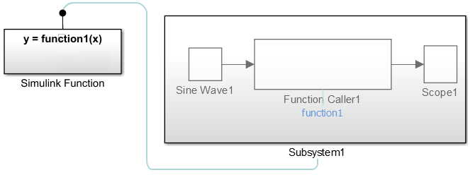
What Are Simulink Function Callers?
A Simulink function caller invokes the execution of a Simulink function from anywhere in a model or chart hierarchy.
- Function Caller block — Call a function defined in Simulink or exported from Stateflow. See Function Caller .
- Stateflow chart transition — In a Stateflow chart, call a function defined in Simulink or exported from Stateflow.
- MATLAB Function block — Call a function from a MATLAB language script.
- S-Function block — Call a function using system methods. See ssDeclareFunctionCaller and ssCallSimulinkFunction .
- MATLAB System block — Call a function using a System object™ and the MATLAB language.
Connect to Local Signals
In addition to Argument Inport and Argument Outport blocks, a Simulink Function block can interface to signals in the local environment of the block through Inport or Outport blocks. These signals are hidden from the caller. You can use port blocks to connect and communicate between two Simulink Function blocks or connect to root Inport and Outport blocks that represent external I/O.

You can also connect the Outport blocks to sink blocks that include logging ( To File , To Workspace ) and viewing ( Scope , Display ) blocks. However, these blocks execute last after all other blocks.
A Simulink Function block can output a function-call event to an Outport block.
Reusable Logic with Functions
Use functions when you need reusable logic across a model hierarchy. Consider an example where a Simulink Function with reusable logic is defined in a Stateflow chart.

You can move the reusable logic from inside the Stateflow chart to a Simulink Function block. The logic is then reusable by function callers in Simulink subsystems (Subsystem and Model blocks) and in Stateflow charts at any level in the model hierarchy.

The result is added flexibility for structuring your model for reuse.
Input and output argument names ( x2 , y2 ) for calling a function from a Stateflow chart do not have to match the argument names in the function prototype ( u , y ) of a Simulink Function block.
Input/Output Argument Behavior
The function prototype for a Simulink Function block can have identical input and output arguments. For example, a function that filters noise could input a signal and then return the signal after filtering.
You can call the function with a Function Caller block and add noise to a test signal to verify the function algorithm.

When generating code for this model, the input argument for the Simulink Function block passes a pointer to the signal, not a copy of the signal value.
void filter(real_T *rtuy_mySignal) < . . .
*rtuy_mySignal = model_P.DiscreteFilter_NumCoef * DiscreteFilter_tmp; >
Shared Resources with Functions
Use functions when you model a shared resource, such as a printer. The model slexPrinterExample uses Simulink Function blocks as a common interface between multiple computers and a single Stateflow chart that models a printer process.

How a Function Caller Identifies a Function
The function interface uses MATLAB syntax to define its input and output arguments. The name of the function is a valid ANSI ® C identifier. The model hierarchy can contain only one function definition with the identified function name. Simulink verifies that:
- The arguments in the Function prototype parameter for a Function Caller block matches the arguments specified in the function. For example, a function with two input arguments and one output argument appears as:
Reasons to Use a Simulink Function Block
Function-Call Subsystem blocks with direct signal connections for triggering provide better signal traceability than Simulink Function blocks, but Simulink Function blocks have other advantages.
- Eliminate routing of signal lines. The Function Caller block allows you to execute functions defined with a Simulink Function block without a connecting signal line. In addition, functions and their callers can reside in different models or subsystems. This approach eliminates signal routing problems through a hierarchical model structure and allows greater reuse of model components.
- Use multiple callers to the same function. Multiple Function Caller blocks or Stateflow charts can call the same function. If the function contains state (for example, a Unit Delay block), the state is shared between the different callers.
- Separate function interface from function definition. Functions separate their interface (input and output arguments) from their implementation. Therefore, you can define a function using a Simulink Function block, an exported graphical function from Stateflow, or an exported MATLAB function from Stateflow. The caller does not need to know how or where the function was implemented.
Choose a Simulink Function or Reusable Subsystem
A consideration for using a Simulink Function block or a Subsystem block has to do with shared state between function calls. A Simulink Function block has shared state while a Subsystem block, even if specified as a reusable function, does not.
- For a Simulink Function block, when one block has multiple callers, code is always generated for one function. If the Simulink Function block contains blocks with state (for example, Delay or Memory ), the state is persistent and shared between function callers. In this case, the order of calls is an important consideration.
- For a Subsystem block, when a block has multiple instances and is configured as a reusable function, code is usually generated for one function as an optimization. If the Subsystem block contains blocks with state, code is still generated for one function, but a different state variable is passed to the function. State is not shared between the instances.
When Not to Use a Simulink Function Block
Simulink Function blocks allow you to implement functions graphically, but sometimes using a Simulink Function block is not the best solution.
For example, when modeling a PID controller or a digital filter and you have to model the equations defining the dynamic system. Use an S-Function , Subsystem , or Model block to implement systems of equations, but do not use a Simulink Function block, because these conditions can occur:
- Persistence of state between function calls. If a Simulink Function block contains any blocks with state (for example, Unit Delay or Memory ), then their state values are persistent between calls to the function. If there are multiple calls to that function, the state values are also persistent between the calls originating from different callers.
- Inheriting continuous sample time. A Simulink Function block cannot inherit a continuous sample time. Therefore, do not use this block in systems that use continuous sample times to model continuous system equations.
Tracing Simulink Functions
Visually display connections between a Simulink function and their callers with lines that connect callers to functions:
- Turning on/off tracing lines — On the Debug tab, select Information Overlays
 . From the drop-down box, select Function Connectors.
 - Direction of tracing lines — Lines connected at the bottom of a block are from a function caller. Lines connected at the top of a block are to a Simulink function or a subsystem containing the function.


Navigate from a caller in a subsystem to a function by first opening the subsystem, and then clicking a link to the function.

Monitor Ink Status on a Shared Printer Using Simulink Functions
After selecting Function Connectors, the model slexPrinterExample shows the relationships between callers and functions.
In this example, the Function Caller in the Simulink Function block addPrintJob , calls the exported Stateflow function queuePrintJob . The subchart Busy calls the Simulink Function block printerInk . Tracing lines are drawn into and out of the Stateflow chart.

Highlight and Animate Function Calls
Use animation to highlight function calls.
This example shows a still of an animated Simulink function call.

To access animation, in the toolstrip, on the Debug tab, in the Event Animation section, set the animation speed to Slow , Medium , or Fast .
Event Animation is visible when you have event blocks in your model, such as blocks from the Messages & Events library, Stateflow charts, Function-Call Subsystem blocks, Simulink functions, or SimEvents ® blocks.
See Also
Related Topics
Simulink
Simulink is a block diagram environment used to design systems with multidomain models, simulate before moving to hardware, and deploy without writing code.
Simulink is for Model-Based Design
From Concept to Operation
To transform development of complex systems, market-leading companies adopt Model-Based Design by systematically using models throughout the entire process.
- Use a virtual model to simulate and test your system early and often
- Validate your design with physical models, Hardware-in-the-Loop testing, and rapid prototyping
- Generate production-quality C, C++, CUDA, PLC, Verilog, and VHDL code and deploy directly to your embedded system
- Maintain a digital thread with traceability through requirements, system architecture, component design, code and tests
- Extend models to systems in operation to perform predictive maintenance and fault analysis
Simulink is for Simulation
Design and simulate your system before moving to hardware
Explore a wide design space and test your systems early with multidomain modeling and simulation.
- Quickly evaluate multiple design ideas in one multidomain simulation environment
- Simulate large-scale system models with reusable components and libraries including specialized, third-party modeling tools
- Deploy simulation models for desktop, real-time, and Hardware-in-the-Loop testing
- Run large simulations on multicore desktops, clusters, and the cloud

Simulink is for Model-Based Systems Engineering
Design, analyze, and test system and software architectures
Model-based systems engineering (MBSE) is the application of models to support the full system lifecycle. Simulink bridges development from requirements and system architecture to detailed component design, implementation, and testing.
- Capture and decompose requirements
- Define and elaborate specifications for components, compositions, and architectures
- Establish a single-source for architecture and component-level interfaces
- Perform analysis and trade studies using MATLAB
- Validate requirements and verify system architectures using simulation-based tests
Simulink is for Agile Software Development
Agile software development helps teams deliver value to their customers faster using short iteration cycles with an emphasis on continuous integration and team collaboration. Simulation, automated testing, and code generation shorten the development cycle, enabling you to become a successful Agile team.
- Develop and run simulation tests in an automation server to continuously verify new design iterations
- Perform more analysis and testing on the desktop before going to hardware
- Deliver working software through simulations that customers can evaluate
- Respond to changing requirements quicky through model updates and simulation
- Make progress visible to key stakeholders with automated reports and dashboards