Programming an AVR ATmega328P with an Arduino
An Arduino can be used to flash a standalone ATmega328P microcontroller without the Arduino bootloader. In this article we will cover:
- Setting up the Arduino IDE to program a standalone ATmega328P microcontroller
- Preparing the Arduino Uno to work as an in-system programmer
- Programming an ATmega328P with a blinking LED program
Introduction
The ATmega328P is the microcontroller that powers the Arduino Uno development board. The Arduino board makes it easy to interface with the pins on the ATmega328P while adding extra features that don’t come with the standalone microcontroller, including a USB serial interface and 16 MHz clock. Prototyping is a great use for an Arduino board as it allows for quick and easy iterations of a design, but for completed projects it can often be overkill depending on the features used. An official Arduino Uno costs over $20 (although clones can be found on eBay for $10 or less) while a standalone ATmega328P costs about $2. So once you have completed prototyping a project with the Arduino, you can transition the project to using a standalone ATmega328P instead.
The first problem that may become obvious though is that you can’t connect the ATmega328P directly to your computer to upload programs to it. A separate programmer is needed. Luckily, if you have an Arduino, you already have what you need since the Arduino itself can be used as a programmer for the ATmega328P (and many other AVR microcontrollers). This article shows how to program a standalone ATmega328P using an Arduino and the Arduino IDE. We will also be using straight C code without any of the built in functions the Arduino IDE provides.
Components
To flash an ATmega328P chip with an Arduino you only need a few simple components that you likely already have if you use an Arduino including:
For this example I’ll be flashing the ATmega328P with a simple blinking LED program so I also need the following components:
Hardware Setup
For this project we will setup the standalone ATmega328P on a breadboard with two LEDs connected to seperate pins that will flash back and forth at changing speeds. The two LEDs will be connected to pin numbers 14 and 15 on the ATmega328P, which correspond to pins PB0 and PB1. Since we are using straight C code for the program, this means we only have to concern ourselves with PORTB for controlling the pins.

Place the ATmega328P in the middle of the breadboard with the rows of pins straddling the centerline as shown below.
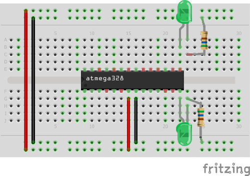
Connect pin 7 (VCC) to the power rail and pin 7 (GND) to the ground rail. These serve as the power and ground to the ATmega328P. Finally connect the LEDs to pins 14 (PB0) and 15 (PB1) as shown and use a resistor to connect them to the ground rails.
The Code
To write the code, we will use the Arduino IDE. Open up the Arduino IDE and create a new sketch. Delete all the pre-populated code in it since when using C directly to program the ATmega328P we do not need the setup() and loop() routines that the Arduino IDE automatically provides.
To get the LEDs to blink, we will use the following code. Put this code in the blank sketch and save it as «doubleLED_blink».
#include #include int main(void) < DDRB = 0b00000011; // Sets PB0 and PB1 to outputs while(1)< PORTB = 0b00000001; // Turns on only PB0 _delay_ms(2000); // Delays 2000ms (2s) PORTB = 0b00000010; // Turns on only PB1 _delay_ms(2000); // Delays 2000ms (2s) PORTB = 0b00000001; // Turns on only PB0 _delay_ms(1000); // Delays 1000ms (1s) PORTB = 0b00000010; // Turns on only PB1 _delay_ms(1000); // Delays 1000ms (1s) PORTB = 0b00000001; // Turns on only PB0 _delay_ms(500); // Delays 500ms (0.5s) PORTB = 0b00000010; // Turns on only PB1 _delay_ms(500); // Delays 500ms (0.5s) >return(0); > Setting up the Arduino IDE
Before we can program our code into the ATmega328 we need to do some additional setup in the Arduino IDE to get the Arduino Uno to function as a programmer. Since the ATmega328P that we are flashing does not have the same configuration as the microcontroller on the Arduino, we need to install an additional hardware configuration in the Arduino IDE as outlined below:
- Download the breadboard-1-6-x configuation here.
- Determine the location of your Arduino sketchbook folder by opening the Arduino IDE, going to File, selecting Preferences and then looking at the Sketchbook location.
- Go to the location of your sketchbook folder and create a «hardware» folder if one does not exist already.
- Extract the «breadboard» folder from the «breadboard-1-6-x» zip file and move it into the newly created «hardware» folder. The «hardware» folder should now have the «breadboard» folder in it.
- Restart the Arduino IDE
- In the Arduino IDE, confirm that setup was completed correctly by going to Tools > Board. You should now see «ATmega328 on a breadboard (8 MHz internal clock)» as an option in the boards list.
As stated in the name, the configuration we just loaded into the Arduino IDE (ATmega328 on a breadboard (8 MHz internal clock)), assumes that the internal clock speed of the ATmega328P is set to 8MHz. While 8MHz is one of the clock speeds of the microcontroller, it is likely not operating at that speed. An ATmega328P straight from the manufacturer is set to run at 1MHz. This difference between what the IDE thinks the clock speed is set to and what the Atmega328P is actually running at will mean the delay times in the code will be incorrect. This can be changed by modifying the ATmega328P clock speed by what are called the «fuse bits» but that takes some extra work. The easier way is to tell the IDE what speed the ATmega328P is at. This is done by the following:
- Go to the «hardware» folder we just created when loading the configuration and open the «breadboard» folder, then open the «avr» folder.
- Open the «boards.txt» file
- In the file, find the line that says «atmega328bb.build.f_cpu=8000000L»
- Change the line to the following «atmega328bb.build.f_cpu=1000000L»
- Save and close the file
Now when the program is loaded onto the ATmega328P it will know the microcontroller is running at 1MHz instead of 8MHz and the delay times will be correct.
Preparing and Connecting the Arduino
The Arduino Uno itself needs to have a special sketch uploaded to it for it to be used as in-system programmer (ISP). Once uploaded, it will be able to program the ATmega328P. The Arduino is setup to be an ISP by performing the following steps:
- Open up the ArduinoISP sketch by going to File -> Examples -> ArduinoISP -> «ArduinoISP»
- Upload the ArduinoISP sketch to your Arduino as you would normally with any other sketch
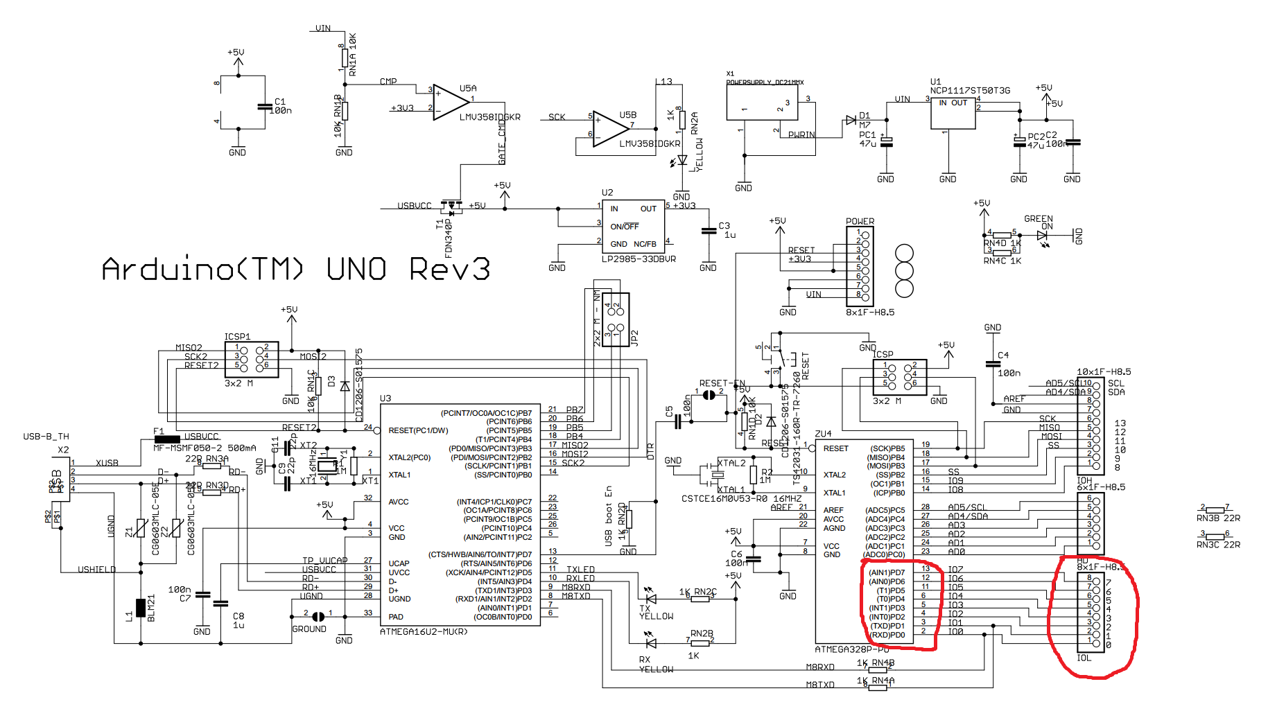
With the Arduino now setup as an ISP, we can use it to program the ATmega328P. We will use the Serial Peripheral Interface (SPI) bus to connect the Arduino to the ATmega328P by properly connecting the SPI pins. This is where things can get tricky because the header pin numbers on the Arduino do not directly match the pin numbers on the ATmega328P even though the Arduino is using an ATmega328P itself. To make sure we are connecting the correct pins we need to compare the Arduino pin numbers to those of the ATmega328P. The picture below shows how the Arduino pins compare to our ATmega328P for SPI to work.
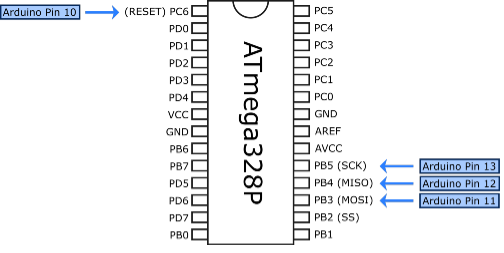
The SPI pins names are SCK, MISO, MOSI, and SS. From the diagram we can see that we need to connect the Arduino pins to the ATmega328P pins as follows:
- Arduino Pin 13 → PB5 (SCK)
- Arduino Pin 12 → PB4 (MISO)
- Arduino Pin 11 → PB3 (MOSI)
- Arduino Pin 10 → PC6 (SS to RESET)
For SCK, MISO, and MOSI we simply connect those pins on the Arduino to the same ones on the ATmega328P. But the SS on the Arduino doesn’t go to the SS on the ATmega328P, instead it is connected to RESET (PC6) on the ATmega328P. This is necessary for the ATmega328P to enter programming mode. Below we see how the pins should be connected.
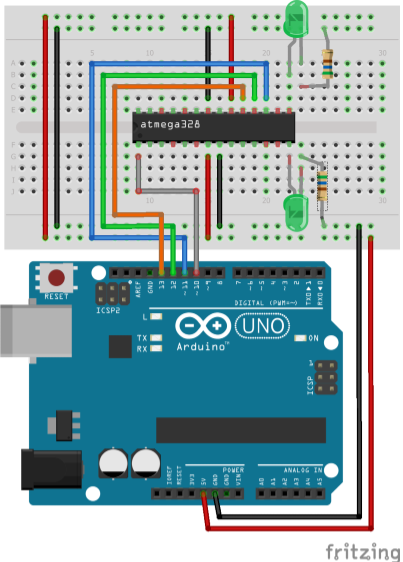
We are also using the 5V and GND pins on the Arduino to power the ATmega328P, therefore these pins need to be connected to the breadboard power and ground rails as shown.
Programming the ATmega328P
Before we can flash the program into the ATmega328P, we need to make sure the correct board and programmer are selected in the Arduino IDE by doing the following:
- Select the correct board in the Arduino IDE by going to Tools > Board and selecting «ATmega328 on a breadboard (8 MHz internal clock)»
- Select the correct programmer in the Arduino IDE by going to Tools > Programmer and selecting «Arduino as ISP»
With the board and programmer correctly set, we can now flash the program into the ATmega328P. Open up the «doubleLEB_blink» sketch we created earlier. The go to «Sketch» and select «Upload Using Programmer». If the ATmega328P is successfully programmed we should now see the LEDs blinking back and forth at faster speeds until the loop completes and starts over.
Summary
In this article we covered how an Arduino Uno can be used as an in-system programmer to program a standalone ATmega328P. By performing some simple modifications to the Arduino IDE configuration and connecting the Uno to the ATmega328P on a breadboard, we can easily load our programs onto the microcontroller while also powering it directly from the Arduino. Now you can prototype and develop custom programs for the microcontroller without needing all the extra features of the Arudino while utilizing a smaller package once your design is finalized.
Helpful Resources
Программирование Arduino с помощью ISP программатора
Программировать Arduino Uno на «чистом» C или на Ассемблере не намного сложнее, чем с использованием стандартного языка программирования для Arduino. При этом вы можете сильно выиграть в производительности и сократить размер вашей программы. Далее речь пойдет о том, как перепрошить Arduino Uno R3 с использованием ISP программатора и AVR Studio 6.2.
Итак, нам понадобится Arduino Uno R3, любой ISP программатор совместимый с Atmel Studio 6, один светодиод и резистор, например, на 250 Ом. Для программирования Arduino я использую универсальный программатор Atmel ICE. Как я уже говорил, вы можете использовать любой программатор ISP для программирования Arduino. Список поддерживаемых программаторов вы можете посмотреть прямо в Atmel Studio.
Все знают, что в Arduino Uno R3 используется микроконтроллер ATmega328P-PU. Именно его мы и будем программировать. Фактически после записи нашей программы у нас будет уже не Arduino, а просто микроконтроллер с обвязкой. Так как мы сотрем загрузчик Arduino.
К сожалению, микроконтроллер ATmega328P-PU не поддерживает «продвинутую» отладку через JTAG. Вы, конечно, можете дебажить свой Arduino в Arduino Micro с точками останова и выводом значений в output (нужно явно запрашивать, что хотите получить), но такой подход не всегда удобен, к тому же в Atmel Studio есть значительно более совершенные средства отладки (просмотр состояний регистров, мониторинг памяти, и т.д.). По этому мы ограничимся тем, что будем просто прошивать наш контроллер по ISP.
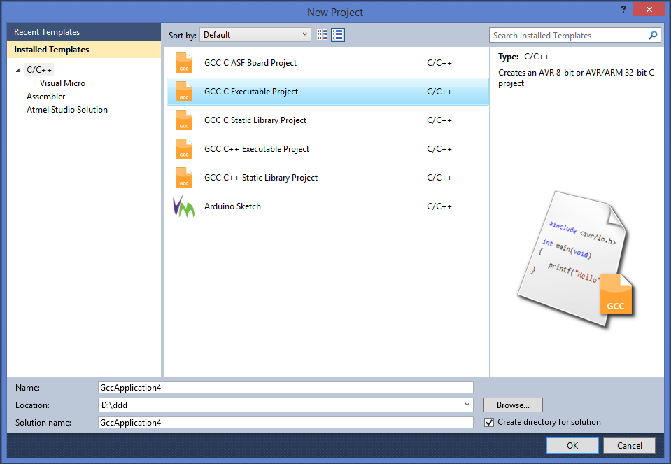
Откройте Atmel Studio и выберите проект GCC C Exacutable Project, так как показано на рисунке.
Отлично, проект создан. Теперь нужно подключить наш программатор. Я использую Atmel ICE. Это универсальный программатор, который подходит для большинства микроконтроллеров AVR и ARM от Atmel. Подключаем программатор к компьютеру, затем в Atmel Studio выбираем пункт Tools -> Device Programming. Важно! Если у вас русская Windows то не создавайте проект в моих документах и вообще с папках с русским названием. Лучше создайте на диске отдельную папку с названием без кириллицы, например D:\myprog. Так же не забудьте запустить студию с правами администратора.
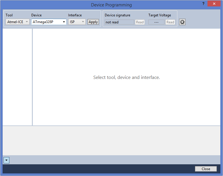
В открывшимся окне выбираем следующие опции: Tool — устройство для программирования\отладки в данном случае Atmel ICE, Device — микроконтроллер, который собираемся программировать, Interface — интерфейс через который наш программатор будет прошивать\отлаживать микроконтроллер, в данном случае доступен только ISP.
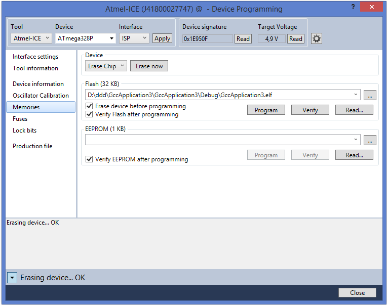
Нажимаем кнопочку Read для получения идентификатора устройства и его рабочего напряжения. Если Arduino подключена правильно, то вы должны получить номер устройства, например 0x1E950F и напряжение 4.9V.
Нажимаем Apply. После этого должны появится настройки для программатора так как показано на рисунке ниже.

Далее выполняем следующие действия. Меняем ISP Clock на 250. Затем переходим в раздел Memories и нажимаем кнопку Erase now. Важно! После этого действия вы не сможете использовать свой Arduino совместно с Arduino IDE, так как загрузчик будет удален.
Теперь у нас все готово для программирования. Давайте напишем небольшую программу для мигания светодиодом.
Вставьте в макетную плату светодиод и подключите его через токоограничивающий резистор. Положительную лапку светодиода соедините с цифровым выходом 5 на Arduino.
Теперь нужно разобраться какая ножка микроконтроллера соответствует выводу на плате. Для этого нам понадобится datasheet.
Так как мы хотим управлять светодиодом с помощью 6-го вывода на Arduino мы будем использовать регистр PORTD и 5-й бит который подаст напряжение на 11 ножку нашего микроконтроллера.
Поместите следующий код в файл с кодом проекта.
#include #define F_CPU 16000000UL //16MHz #include int main(void) < DDRD |= 1> Нажимаем «Ctrl + Alt + F5» или выбираем в меню пункт Debug -> Start Without Debugging. Светодиод начнет мигать!
Вот, собственно, и все… Обратите внимание на скорость прошивки и на размер программы. Данный пример занимает около 186 байт, что составляет 0.6% от объема памяти контроллера.