- Creating a Serial PIC Programmer from an Arduino (Part 1)
- Hardware Design
- Serial Communication with an Arduino
- Setting the Clock Speed
- Generating the Clock Signal
- Arduino программатор PIC-ов.
- Saved searches
- Use saved searches to filter your results more quickly
- magedrifaat/Arduino-PIC-programmer
- Name already in use
- Sign In Required
- Launching GitHub Desktop
- Launching GitHub Desktop
- Launching Xcode
- Launching Visual Studio Code
- Latest commit
- Git stats
- Files
- README.md
Creating a Serial PIC Programmer from an Arduino (Part 1)
A while back I bought a couple of PIC16F57 (DIP) chips because they were dirt cheap. I figured someday I could use these in something. Yes, I know, this is a horrible way to actually build something and a great way to accumulate junk. However, this time the bet paid off! Only about a year or two too late; but that’s beside the point. The problem I now had was that I didn’t have a PIC programmer.
When I bought these chips I figured I could easily rig a board up to the chip via USB. Lo and behold, I didn’t read the docs properly; this chipset doesn’t have a USB to serial interface. Instead, it only supports Microchip’s In-Circuit Serial Programming (ICSP) protocol via direct serial communication. Rather than spend the $40 to buy a PIC programmer (thus, accumulating even more junk I don’t need), I decided to think about how I could make this happen.
Glancing at some of my extra devices lying around, I noticed an unused Arduino. This is how the idea for this project came to life. Believe me, the irony of programming a PIC chip with an ATMega is not lost on me. So for all of you asking, «why would anyone do this?» the answer is two-fold. First, I didn’t want to accumulate even more electronics I would not use often. Second, these exercises are just fun from time to time!
Hardware Design
My prototype’s hardware design is targeted to using an Arduino Uno (rev 3) and a PIC16F57. Assuming the protocol looks the same for other ICSP devices, a more reusable platform could emerge from a common connector interface. Likewise, for other one-offs it could easily be adapted for different pinouts. Today, however, I just have the direct design for interfacing these two devices:

Overall, the design can’t get much simpler. For power I have two voltage sources. The Arduino is USB-powered and the 5V output powers the PIC chip. Similarly, I have a separate +12V source for entering/exiting PIC programming mode. For communication, I have tied the serial communication pins from the Arduino directly to the PIC device.
The most complicated portion of this design is the transistor configuration; though even this is straightforward. I use the transistor to switch the 12V supply to the PIC chip. If I drive the Arduino pin 13 high, the 12V source shunts to ground. Otherwise, 12V is supplied to the MCLR pin on the PIC chip. I make no claims that this is the most efficient design (either via layout or power consumption), but it’s my first working prototype.
Serial Communication with an Arduino
Arduino has made serial communication pretty trivial. The only problem is that the Arduino’s serial communication ports are UART. That is to say, the serial communication is asynchronous. The specification for programming a PIC chip with ICSP clearly states a need for a highly controlled clock for synchronous serial communication. This means that the Arduino’s Serial interface won’t work for us. As a result, we will go on to use the Arduino to generate our own serial clock and also signal the data bits accordingly.
Setting the Clock Speed
The first task to managing our own serial communication with the Arduino is to select an appropriate clock speed. The key to choosing this speed was finding a suitable trade-off between programming speed (i.e. fast baud rate) vs. computation speed on the Arduino (i.e. cycles of computation between each clock tick).
Remember, the Arduino is ultimately running an infinite loop and isn’t actually doing any parallel computation. This means that the amount of time it takes to perform all of your logic for switching data bits must be negligible between clock ticks. If your computation time is longer than or close to the clock ticking frequency, the computation will actually impact the clock’s ability to tick steadily. As a rule of thumb, you can always set your clock rate to have a period that is roughly 1 to 2 orders of magnitude than your total computation.
Taking these factors into account, I chose 9600 baud (or a clock at 9.6KHz). To perform all the logic required for sending the appropriate programming data bits, I estimated somewhere in the 100’s of nanoseconds to 1’s of microseconds for computation. Giving myself some headroom, I selected a standard baud rate that was roughly two orders of magnitude larger than my computation estimate. Namely, a period of 104 microseconds corresponds to a 9.6KHz clock.
After completing the project I could have optimized my clock speed. However, that was unnecessary for this project. The clock rate I had selected worked well. The 9600 baud rate is fast enough for timely programming the device because we don’t have much data to transmit. Similarly, it provides us a lot of headroom to experiment with different types of computation.
Generating the Clock Signal
While this discussion has primarily focused on the design decisions involved in choosing a clock signal rate, how did we generate it? The process really comes down to toggling a GPIO pin on the Arduino. In our specific implementation, I chose pin 2 on the Arduino. While you can refer to the code for more specific details, an outline of this process follows:
Arduino программатор PIC-ов.
Вы используете устаревший браузер. Этот и другие сайты могут отображаться в нём некорректно.
Вам необходимо обновить браузер или попробовать использовать другой.

Иногда встречаются очень интересные проекты выполненные на микросхемах PIC. Это микроконтроллеры с RISC архитектурой,
производимые фирмой Microchip Technology. Программаторы для PIC сложные и дорогие. Чтобы сделать программатор для PIC, нужен программатор для PIC, замкнутый круг для самодельщина. Но у нас есть Arduina! Сделаем из ардуины очень дешевый, очень простой, но работающий как очень дорогие HVSP программаторы микроконтроллеров от Microchip Technology.
HVSP — это High Voltage Serial Programming, высоковольтное последовательное программирование. Высоковольтное программирование позволяет сделать рабочим окирпиченный PIC контроллер из за неправильно выставленных фьюзов или заблокированных ног используемых при низковольтном программировании. В общем без разницы в каком состоянии Вам пришлют хитрые китайцы микроконтроллер, главное, чтобы он был аппаратно живой. А разлочить можно и ардуиной. Запрограммировать можно и ардуиной.
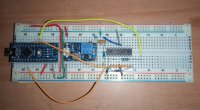
Пример работы программатора сделанного из ардуино нано в макете с парой дополнительных деталей которые можно выдрать из старой техники. Единственное для удобства я использовал повышающий преобразователь для получения 13V нужных для высоковольтного программирования. Удобство заключается в том, что просто вставляете программатор в USB и работаете не заморачиваясь на необходимости подачи внешнего питания. Иначе просто можно подать это напряжение от внешнего блока питания и схема станет еще проще.
Saved searches
Use saved searches to filter your results more quickly
You signed in with another tab or window. Reload to refresh your session. You signed out in another tab or window. Reload to refresh your session. You switched accounts on another tab or window. Reload to refresh your session.
Program PIC devices using Arduino
magedrifaat/Arduino-PIC-programmer
This commit does not belong to any branch on this repository, and may belong to a fork outside of the repository.
Name already in use
A tag already exists with the provided branch name. Many Git commands accept both tag and branch names, so creating this branch may cause unexpected behavior. Are you sure you want to create this branch?
Sign In Required
Please sign in to use Codespaces.
Launching GitHub Desktop
If nothing happens, download GitHub Desktop and try again.
Launching GitHub Desktop
If nothing happens, download GitHub Desktop and try again.
Launching Xcode
If nothing happens, download Xcode and try again.
Launching Visual Studio Code
Your codespace will open once ready.
There was a problem preparing your codespace, please try again.
Latest commit
Git stats
Files
Failed to load latest commit information.
README.md
This projects enables programming PIC devices using Arduino only i.e. it should (in ideal cases) replace pickit and other programming devices. It currently only supports a very small number of devices which are PIC16F87XA family and uses Low voltage programming mode for obvious reasons. It should be able to work with some other devices as well but that is not guaranteed. Also, this only supports HEX files of Intel HEX format (which is the most common format, I believe).
Support for more devices should be added in the next updates.
All you need to start using this project is:
- An Arduino uno (or any other Arduino but probably with a little modification to the pin numbers in the sketch).
- The Arduino IDE.
- And any python environment.
After you have installed the Arduino IDE and any python environment you need to install pyserial library in your python environment. It is usually done by typing this command in your console:
But it might not be that simple depending on your environment so if it didn’t work just search how to install a library in your environment.
Next thing is you get the sketch file and the hextoserial.py file from this project, upload the sketch to the arduino using the IDE, connect the Arduino to the PIC as described in the beginning of the sketch.

Having connected the arduino to the PIC as described in the sketch, and the arduino connected to your computer using USB, find out which port is your arduino connected to on your computer. This can be seen from the arduino IDE by opening port under Tools menu, You should find the port name (In windows, It is typically COMX where X is the port number), Remember that port name for the next step.
Now run hextoserial.py in your environment. You will be asked for the name of the port where the arduino is connected. After entering it you will be asked to enter the full path of the hex file. Then it asks you to enter P for programming, V for verification or D for verification with debugging, You should start by Entering P then after the programming is done enter V.
If the programming was done correctly the verification process shouldn’t produce any error messages and end with «Verification done», otherwise you will get an error message saying verification failed. You may then try reprogramming by entering P or verify with debugging using D to show you the difference between the file and the data it reads from the chip.
After you are done stop the process in the console, this should close the serial communication with the arduino and close the hex file.

Here is a circuit diagram of the connection:
Make sure you put a 10K resistor on the MCLR pin and a 100nF capacitor to the ground as shown above.

Connecting the arduino to the computer and uploading the sketch, then running the python file:

Entering the communication port and the path to the hex file:

Choosing P to program then V to verify programming:
And that’s it. Now connect the pic in its normal connection or if it is on a board remove the connections to the arduino and restart.