Arduino.ru
Собираю пушку для ребенка пульками Nerf. Подавать патроны буду с помощью сервомотора, а запускать их буду с помощью бесколлекторного двигателя. Искал в интернете код для управления и нашел.
#include // создание объекта Servo motor; Servo myservo; // create servo object to control a servo //Пин подключения мотора int mot_pin = 9; //Максимальное значение ШИМ 2.3 мс int max_pwm = 2300; //Минимальное значени ШИМ 0.8 мс int min_pwm = 800; void setup() < // запуск последовательного порта Serial.begin(9600); myservo.attach(3); // инициализация мотора motor.attach(mot_pin); // калибровка motor.writeMicroseconds(max_pwm); delay(2000); motor.writeMicroseconds(min_pwm); delay(2000); >void loop()
Но к сожалению никак не могу понять как заставить вращаться двигатель и при этом подавать патроны.
Забыл добавить! Моторы — BR2205, контроллер — bidireetional 20A 2s-4s.
Схему нарисуйте. Возможно мотор неправильно подключили. Или контроллер.
А предварительно тестером пройдитесь по всем соединениям. И по блоку питания, кстати.
есть вероятность что ESC настроен для работы в реверсном режиме, тогда значение 1500 это нейтраль, 2000, вперёд, 1000 — назад, да и программа калибровки написана неправильно.
Постарался нарисовать, но не сказать что хорошо получилось(
Питание всей схемы 5 вольт.
И еще. Пока не включаю в код сервопривод двигатель запускается, но работает несколько секунд и отключается и так по кругу
про 1000 — 2000 сейчас попробую, спасибо))
// скетч калибровки регуляторов ESC // напряжение питания подаваемое на регулятор через цепь простейшего параметрического // стабилизатора на 5 вольт через резистор 1 ком подать на mot_vccPin притянутый к GND // через резистор 10 ком // Калибровка, соединить всё по схеме // 1. Подать питание на ардуино // 2. Подать питание на мотор // 3. мотор пропел одной тональностью, затем второй, через две секунды можно отключать // регулятор откалиброван на значения 1000 - 2000 (стандартные значения) #include Servo motor; //Пин подключения мотора int mot_pin = 9; int mot_vccPin = 10; //Максимальное значение ШИМ 2.0 мс int max_pwm = 2000; //Минимальное значени ШИМ 1.0 мс int min_pwm = 1000; void setup() < // запуск последовательного порта Serial.begin(115200); // инициализация мотора motor.attach(mot_pin); motor.writeMicroseconds(min_pwm); // калибровка while (!digitalRead(mot_vccPin)); // висим в цикле пока не подадим на регулятор питание delay(3000); motor.writeMicroseconds(max_pwm); delay(3000); motor.writeMicroseconds(min_pwm); delay(2000); Serial.println("Регулятор мотора откалиброван"); >void loop() < //Крутимся в цикле - мотор откалиброван и остановлен > Огромное спасибо! Сейчас буду пробовать.
Огромное спасибо! Сейчас буду пробовать.
не проверял, так что результаты в студию, если что не так — поправлю
PS если есть БЭК на регуляторе 5 вольт на пин mod_vccPin можно взять с него
И еще. Пока не включаю в код сервопривод двигатель запускается, но работает несколько секунд и отключается и так по кругу
Начните с того, что запитайте всю электромеханику от отдельного (более мощного) блока питания, а не от Ардуино.
Я думаю что не надо программировать то что не надо программировать.
Купите «turnigy 9x» с приёмником, желательно старую на
Мега2560.
Недавно брал с тремя приемниками коллеге за 50 евро.
Катер он решил переделать двухмоторный без заднего хода.
Сервы и моторы подключаются втыканием разъёмов.
Максимум что вручную сделать — если захочется несколько реле включать то надо наТини13 платку собрать, прошивок и скетчей полный интернет.
Настраивается на компе , можно ваять любые чудеса.
В программе есть симулятор, очень помогает при настройке.
Программа называется eepe
http://www.er9x.com/
Катера, самолёты, коптеры, машинки и всё что угодно.
Я думаю что не надо программировать то что не надо программировать. Купите «turnigy 9x» с приёмником, желательно старую на Мега2560. Недавно брал с тремя приемниками коллеге за 50 евро. Катер он решил переделать двухмоторный без заднего хода. Сервы и моторы подключаются втыканием разъёмов. Максимум что вручную сделать — если захочется несколько реле включать то надо наТини13 платку собрать, прошивок и скетчей полный интернет. Настраивается на компе , можно ваять любые чудеса. В программе есть симулятор, очень помогает при настройке. Программа называется eepe http://www.er9x.com/ Катера, самолёты, коптеры, машинки и всё что угодно.
Спасибо, но очень хочется на ардуино сделать чтобы была большая гибкость! да и просто интересно)
// скетч калибровки регуляторов ESC // напряжение питания подаваемое на регулятор через цепь простейшего параметрического // стабилизатора на 5 вольт через резистор 1 ком подать на mot_vccPin притянутый к GND // через резистор 10 ком // Калибровка, соединить всё по схеме // 1. Подать питание на ардуино // 2. Подать питание на мотор // 3. мотор пропел одной тональностью, затем второй, через две секунды можно отключать // регулятор откалиброван на значения 1000 - 2000 (стандартные значения) #include Servo motor; //Пин подключения мотора int mot_pin = 1; //int mot_vccPin = 10; //Максимальное значение ШИМ 2.0 мс int max_pwm = 2000; //Минимальное значени ШИМ 1.0 мс int min_pwm = 1000; void setup() < // запуск последовательного порта Serial.begin(115200); // инициализация мотора motor.attach(mot_pin); motor.writeMicroseconds(min_pwm); // калибровка // while (!digitalRead(mot_vccPin)); // висим в цикле пока не подадим на регулятор питание // delay(3000); motor.writeMicroseconds(max_pwm); delay(3000); motor.writeMicroseconds(min_pwm); delay(2000); Serial.println("Регулятор мотора откалиброван"); >void loop() < motor.writeMicroseconds(min_pwm); delay(1000); //Крутимся в цикле - мотор откалиброван и остановлен > Всем доброго времени суток! За код спасибо, но ничего не получилось( Он ведет себя странно. Сначала приветствует пиканьем, потом один «пик» и молчит. Если перезагрузить контроллер то он «пикает» второй раз, запускает двигатель и выключает его. Очень странное поведение.
Сейчас попробую залить видео. Только я убрал проверку питания, неудобно ее делать(
Arduino Brushless Motor Control Tutorial | ESC | BLDC
In this tutorial we will learn how to control a brushless motor using Arduino and ESC. In case you want more details how BLDC motors work, you can check the other article or watch the following video which contains explanation of the working principle of a brushless motor and how to control one using Arduino and ESC.
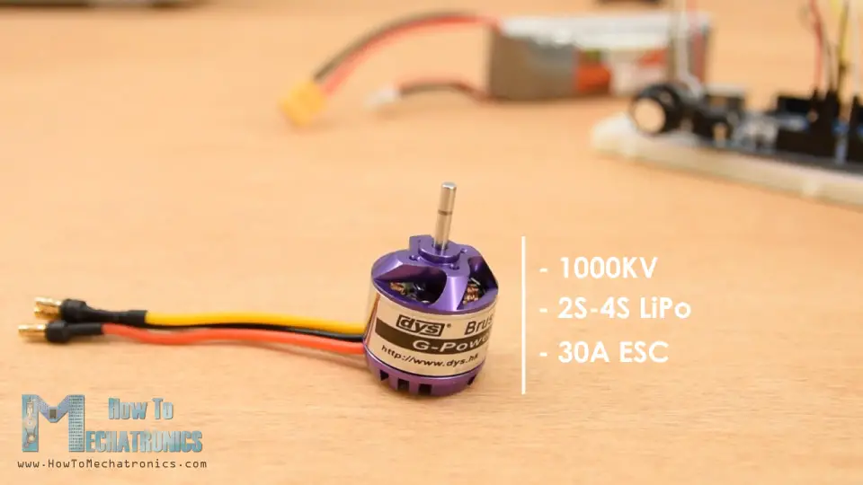
In this case, the 1000KV means that, for example, if we supply the motor with 2S LiPo battery which has a voltage of 7.4 volts, the motor can achieve maximum RPM of 7.4 times 1000, or that’s 7400 RPM.
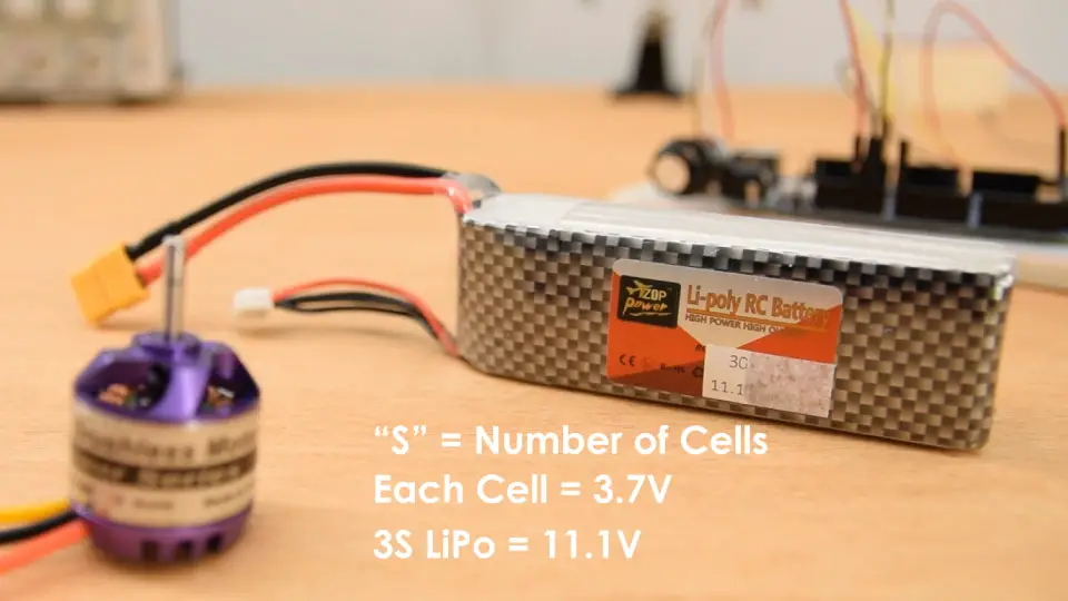
Brushless motors are power hungry and the most common method for powering them is using LiPo batteries. The “S” number of a LiPo battery indicates how many cells the battery has, and each cell has a voltage of 3.7V.
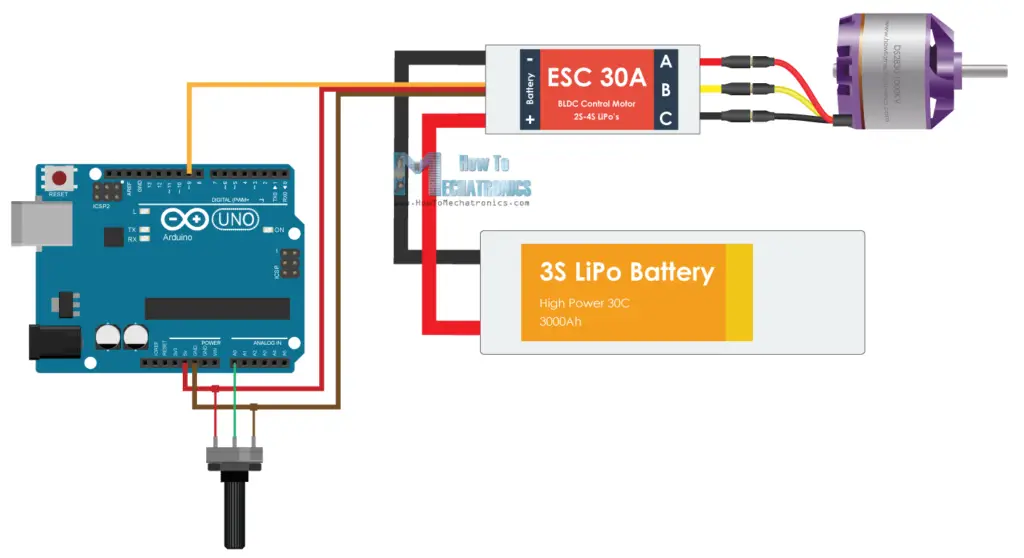
For this example, I will use 3S LiPo battery which has 3 cells and that’s 11.1V. So, I can expect my motor to reach maximum RPM of 11100.
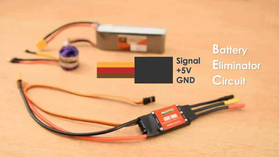
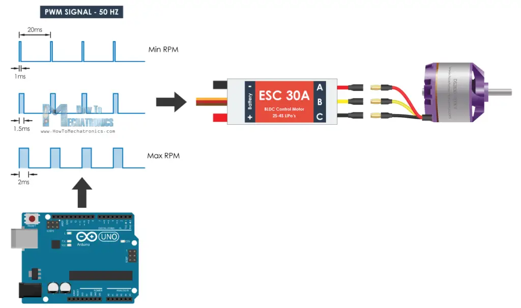
Lastly, here’s a 30A ESC that I will use for this example and match with the motor requirements. On one side the ESC has three wires that control the three phases of the motor and on the other side it has two wires, VCC and GND, for powering.
There is also another set of three wires coming out of the ESC and that’s the signal line, +5V and ground. This feature of the ESC is called Battery Eliminator Circuit and as the name suggests it eliminates the need of separate battery for a microcontroller. With this, the ESC provides regulated 5V which can be used to power our Arduino.
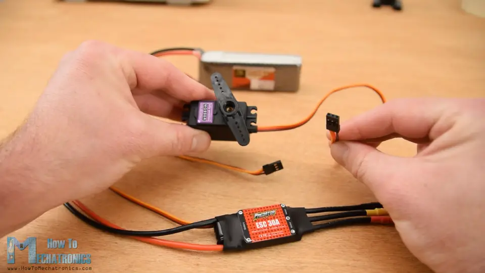
We can notice here that this connection is actually the same as the one we see on Servo motors.
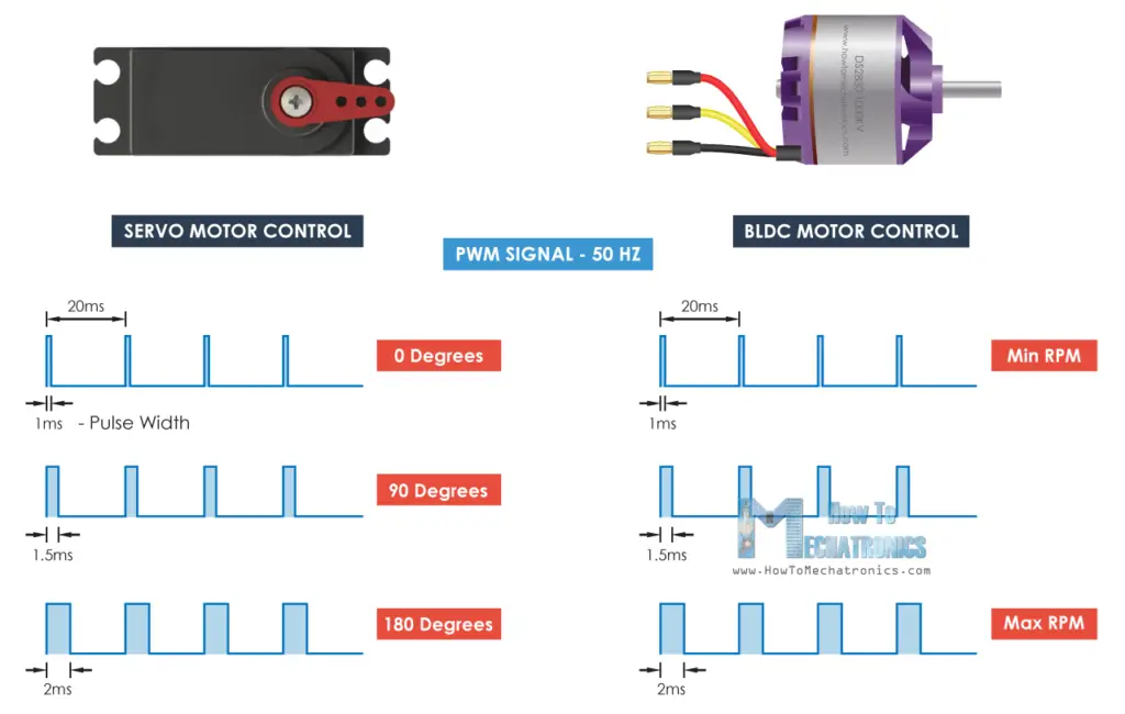
So, controlling a brushless motor using ESC and Arduino is as simple as controlling servo using Arduino. ESCs use the same type of control signal as servo and that’s the standard 50Hz PWM signal.
This very convenient, because for example, when building an RC plane, we usually need both servos and brushless motors and, in this way, we can control them easily with the same type of controller.
So, using the Arduino we just have to generate the 50Hz PWM signal and depending on pulses width or the high state duration which should vary from 1 millisecond to 2 milliseconds, the ESC will drive the motor from minimum to maximum RPM.
Arduino Brushless Motor Control – Circuit Diagram
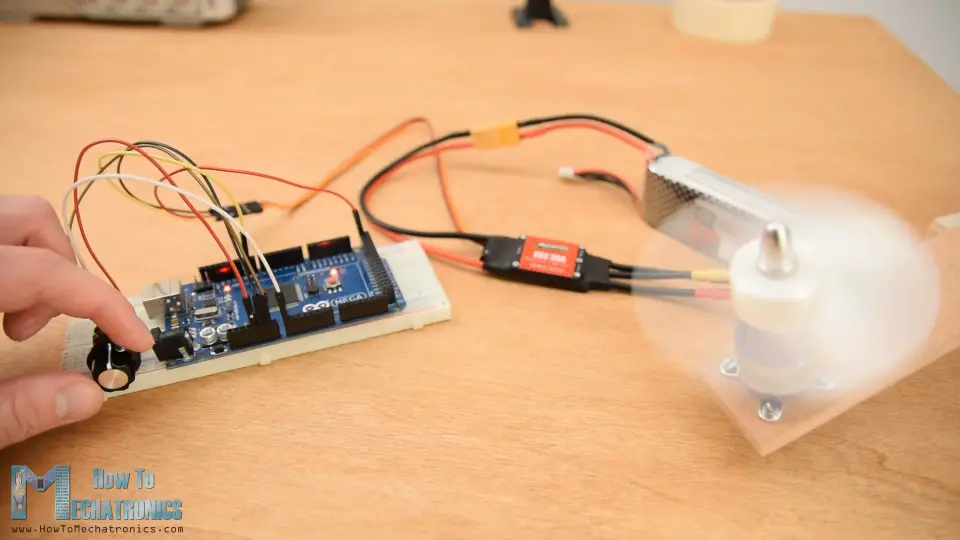
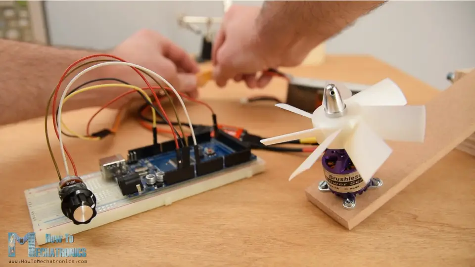
Here’s the circuit diagram for this example. In addition to the ESC we will just use a simple potentiometer for controlling the motor speed.
You can get the components needed for this Arduino Tutorial from the links below:
- Brushless Motor ……………………… Amazon / Banggood / AliExpress
- ESC 30A ……………………………………. Amazon / Banggood / AliExpress
- Li-Po battery ……………….…..…… Amazon / Banggood / AliExpress
- Arduino Board ………………………… Amazon / Banggood / AliExpress
- Potentiometer …………………………. Amazon / Banggood / AliExpress
- Breadboard and Jump Wires … Amazon / Banggood / AliExpress
Disclosure: These are affiliate links. As an Amazon Associate I earn from qualifying purchases.
Arduino Code for BLDC Motor Control
The Arduino code is really simple with just few lines of code.
/* Arduino Brushless Motor Control by Dejan, https://howtomechatronics.com */ #include Servo ESC; // create servo object to control the ESC int potValue; // value from the analog pin void setup() < // Attach the ESC on pin 9 ESC.attach(9,1000,2000); // (pin, min pulse width, max pulse width in microseconds) > void loop() < potValue = analogRead(A0); // reads the value of the potentiometer (value between 0 and 1023) potValue = map(potValue, 0, 1023, 0, 180); // scale it to use it with the servo library (value between 0 and 180) ESC.write(potValue); // Send the signal to the ESC >Code language: Arduino (arduino)Description: So, we need to define the Servo library, because with the servo library we can easily generate the 50Hz PWM signal, otherwise the PWM signals that the Arduino generates are at different frequencies. Then we need to create a servo object for the ESC control and define a variable for storing the analog input from the potentiometer. In the setup section, using the attach() function, we define to which Arduino pin is the control signal of the ESC connected and also define the minimum and maximum pulses width of the PWM signal in microseconds.
In the loop section, first we read the potentiometer, map its value from 0 to 1023 into value from 0 to 180. Then using the write() function we send the signal to the ESC, or generate the 50Hz PWM signal. The values from 0 to 180 correspond to the values from 1000 to 2000 microseconds defined in the setup section.
So, if we upload this code to our Arduino, and then power up everything using the battery, then we can control the speed of the brushless motor of zero to maximum using the potentiometer.
However, there are few things that we should note here. When initially powering the motor, the signal value must be the same or lower than the minimum value of 1 millisecond. This is called arming of the ESC, and the motor makes a confirmation beeps so that we know that it’s properly armed. In case we have higher value when powering, which means we have a throttle up, the ESC won’t start the motor until we throttle down to the correct minimum value. This is very convenient in terms of safety, because the motor won’t start in case we have a throttle up when powering.
ESC Calibration
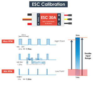
Lastly, let’s explain how ESC calibration works. Every ESC has its own high and low points, and they might slightly vary. For example, the low point might be 1.2 milliseconds and the high point might be 1.9 milliseconds. In such a case, our throttle won’t do anything in the first 20% until it reaches that low point value of 1.2 milliseconds.
To solve this issue, we can calibrate the ESC or set the high and low points as we want. For that purpose, before powering the ESC, first we need to throttle up our potentiometer to maximum or a value at least greater then the current middle point. Then we can power up the ESC, and we will hear few beeps from the motor which actually confirms that we have set the new high point.
Then after 2 seconds, we should move our potentiometer to the position where we what the new low point to be. We will again hear the confirmation beeps and with that we are done with the ESC calibration. Now our throttle will respond right away and we can control the motor within these new two points.
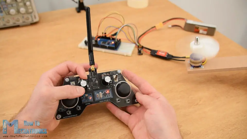
That’s pretty much everything for this tutorial. In case you want to learn how to wirelessly make this Arduino brushless motor control, you can check my previous video where I build and Arduino based RC transmitter and explained how to control BLDC motors using it.
I hope you enjoyed this tutorial and learned something new . Feel free to ask any question in the comments section below and don’t forget to check my collection of Arduino Projects.


