- A Complete Guide to Graphs in Python
- Constructing and using a Graph Data Structure in Python
- Introduction
- Отображение графа на Python с networkx
- Установка networkx
- Терминология
- Создание графа
- Добавим узлы
- Добавим ребра
- Рисуем граф
- Отображение меток
- Применение макетов
- Разметка ребер
- Ориентированный граф
- Настройка узлов
- Очерчивание узлов
- Раскрашивание узлов
A Complete Guide to Graphs in Python
Constructing and using a Graph Data Structure in Python
Introduction
A Graph in programming terms is an Abstract Data Type that acts as a non-linear collection of data elements that contains information about the elements and their connections with each other. This can be represented by G where G = (V, E) and V represents a set of vertices and E is a set of edges connecting those vertices. These edges can represent the relationship between vertices in the form of simply [1, 0] whether there is a connection or not, or a given weight that may represent values such as distance, the strength of the relationship or the number of times they interact. This can be useful when we want to map the relationships between objects, especially when there are multiple relationships, and when we want to search for optimal ways to complete a flow of tasks.
There are two common ways of implementing this Abstract Data Type in Python. The first is the Adjacency Matrix and the second is the Adjacency List. For our purposes, we will be implementing the Adjacency List form, but it is worth understanding why this is the case.
Adjacency Matrix
The Adjacency Matrix in the form of a two-dimensional array is one of the easiest ways to implement a Graph as a Data Structure. This would be represented as:
where each of the rows and columns would represent a vertex in the graph. That value that is stored in the cell representing the intersection of row v and column w indicates if there is an edge from vertex v to vertex w and the size represents the “weight”. When two of these vertices are connected by an edge then we can say that they are adjacent.
The advantage of the adjacency matrix implementation is that it is simple and for small graphs easy to visualise. However, if many of the cells are empty then we have a “sparse” matrix and so we are using large amounts of storage to show little information. Thus, the issue with this implementation is the amount of memory storage used.
Отображение графа на Python с networkx
Граф — это форма визуализации, позволяющая показывать и анализировать отношения между сущностями. Например, рисунок ниже показывает вклад редакторов Википедии на различных языках энциклопедии в июле 2013 года:
Можно сделать несколько наблюдений:
- Английский (en) — основной язык, на который переводятся все остальные языки; в то же время многие англоязычные материалы переводятся на другие языки.
- Китайский (zh) переводится на японский (ja), но не наоборот.
- И китайский, и японский материалы переведены на английский, и наоборот.
Я же расскажу о том, как для отображения графов использовать пакет networkx.
Установка networkx
Чтобы установить этот пакет, используйте команду pip:
Терминология
Прежде чем начать отрисовку графа, полезно знать некоторые основы.
На рисунке ниже показывается направленный граф, также известный как диграф, ребра которого имеют обозначенные стрелками направления.
- Узел — фундаментальный элемент графа, общеизвестный под названием вершина.
- Ребро — соединение узлов графа.
- Неориентированный граф не имеет направления между узлами, то есть не имеет стрелок, а его ребра двунаправлены.
Создание графа
Давайте шаг за шагом создадим граф.
Во-первых, создадим объект класса networkx.classes.graph.Graph:
import networkx as nx G = nx.Graph() print(G) # Graph with 0 nodes and 0 edgesКласс nx.Craph() создает неориентированный граф. Если захочется создать ориентированный, используйте класс nx.DiGraph(directed=True), который возвращает объект networkx.classes.digraph.DiGraph.
В этой статье поговорим об ориентированных графах.
Добавим узлы
Фрагмент кода ниже добавляет три узла без ребер:
G.add_node("Singapore") G.add_node("San Francisco") G.add_node("Tokyo") print(G) # Graph with 3 nodes and 0 edgesПомимо функции add_node() для добавления индивидуальных узлов, чтобы добавить множество узлов, можно воспользоваться функцией add_nodes_from():
G.add_nodes_from(["Riga", "Copenhagen"]) print(G) # Graph with 5 nodes and 0 edgesДобавим ребра
Теперь, когда узлы определены, определим ребра, чтобы соединить их:
G.add_edge("Singapore","San Francisco") G.add_edge("San Francisco","Tokyo") G.add_edges_from( [ ("Riga","Copenhagen"), ("Copenhagen","Singapore"), ("Singapore","Tokyo"), ("Riga","San Francisco"), ("San Francisco","Singapore"), ] ) print(G) # Graph with 5 nodes and 6 edgesКак и узлы, ребра можно добавлять по одному, при помощи add_edge(), или группами — при помощи add_edges_from() со списком кортежей, представляющих каждый узел.
Рисуем граф
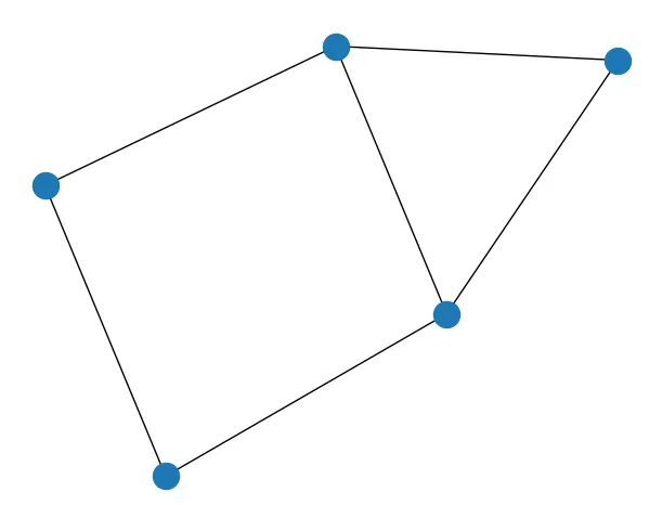
Я покажу основы отображения сетевых графов при помощи пакета networkx. Начнем:
Вот другое изображение того же графа:
Отображение меток
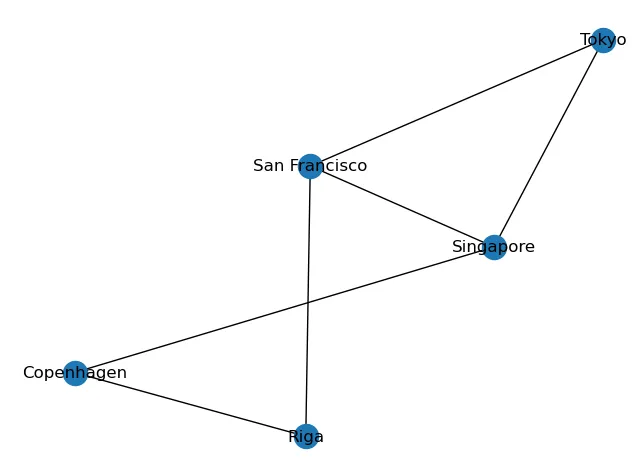
Само собой, граф без меток не очень полезен, если вообще полезен, поэтому давайте отрисуем метки:
nx.draw(G, with_labels = True)- nx.draw_networkx_nodes() — рисует все узлы графа;
- nx.draw_networkx_labels() — рисует метки на каждом узле;
- nx.draw_networkx_edges() — рисует ребра, соединяющие узлы.
И теперь мы видим метку каждого узла:
Применение макетов
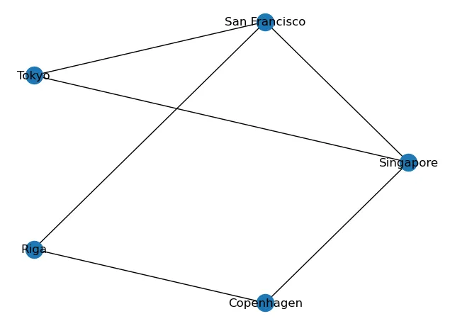
Помните, что функция draw() каждый раз использует разные макеты? Так вот, для графа можно указать конкретный макет:
pos = nx.circular_layout(G) nx.draw(G, pos, with_labels = True)Узлы упорядочены так, что по ним можно очертить круг:
Кроме того, график с круговой компоновкой можно нарисовать с помощью nx.draw_circular(), а не nx.draw():
nx.draw_circular(G, with_labels = True)Можно попробовать другие макеты:
- nx.draw_kamada_kawai(G, with_labels = True);
- nx.draw_planar(G, with_labels = True);
- nx.draw_random(G, with_labels = True);
- nx.draw_spectral(G, with_labels = True);
- nx.draw_spring(G, with_labels = True);
- nx.draw_shell(G, with_labels = True);
Разметка ребер
Ребра можно отметить при помощи nx.draw_networkx_edge_labels(). Фрагмент кода ниже размечает два ребра трех узлов:
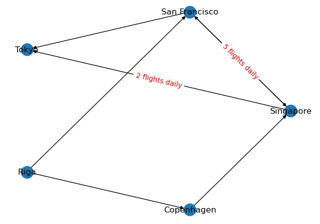
pos = nx.circular_layout(G) nx.draw(G, pos, with_labels = True) nx.draw_networkx_edge_labels( G, pos, edge_labels=< ("Singapore","Tokyo"): '2 flights daily', ("San Francisco","Singapore"): '5 flights daily', >, font_color='red' )Ориентированный граф
Иногда полезно построить ориентированный граф. В нашем примере ребра могут представлять рейсы между двумя городами. Ориентированный граф позволяет увидеть, какие рейсы идут из одного города в другой. Следующий фрагмент кода показывает наш пример в виде ориентированного графа:
import networkx as nx #---directed graph--- G = nx.DiGraph(directed=True) # add nodes G.add_node("Singapore") G.add_node("San Francisco") G.add_node("Tokyo") G.add_nodes_from(["Riga", "Copenhagen"]) # add edges G.add_edge("Singapore","San Francisco") G.add_edge("San Francisco","Tokyo") G.add_edges_from( [ ("Riga","Copenhagen"), ("Copenhagen","Singapore"), ("Singapore","Tokyo"), ("Riga","San Francisco"), ("San Francisco","Singapore"), ] ) # set layout pos = nx.circular_layout(G) # draw graph nx.draw(G, pos, with_labels = True) # draw edge labels nx.draw_networkx_edge_labels( G, pos, edge_labels=< ("Singapore","Tokyo"): '2 flights daily', ("San Francisco","Singapore"): '5 flights daily', >, font_color='red' )Теперь вы видите, что есть рейсы из Сингапура в Сан-Франциско и наоборот; с другой стороны, есть рейсы из Риги в Сан-Франциско, но не наоборот:
Настройка узлов
По умолчанию узлы имеют синий цвет и довольно маленький размер. Настроить узлы и цвет ребра можно, передав словарь в функцию draw():
options = < 'node_color': 'yellow', # color of node 'node_size': 3500, # size of node 'width': 1, # line width of edges 'arrowstyle': '-|>', # array style for directed graph 'arrowsize': 18, # size of arrow 'edge_color':'blue', # edge color > nx.draw(G, pos, with_labels = True, arrows=True, **options)Сейчас узлы желтые и они больше, а ребра синие:
Очерчивание узлов
Если вы хотите обозначить узлы, вам нужно сделать это вручную, используя matplotlib. Следующий фрагмент кода задает размер рисунка 10 на 10 дюймов (ширина и высота), а затем функцией set_edgecolor() рисует контур каждого узла:
pos = nx.circular_layout(G) options = < 'node_color': 'yellow', 'node_size': 8500, 'width': 1, 'arrowstyle': '-|>', 'arrowsize': 18, > nx.draw(G, pos, with_labels = True, arrows=True, **options) ax = plt.gca() ax.collections[0].set_edgecolor("#000000")Теперь каждый узел обведен черным:
Если не установить размер рисунка, граф будет выглядеть так:
Раскрашивание узлов
Чтобы раскрасить каждый узел разными цветами, можно определить цветовую палитру, такую как в bokeh, и установить значение ключу словаря node_color, затем передав его в draw():
from networkx import * import matplotlib.pyplot as plt from bokeh.palettes import Spectral plt.figure(figsize=(8, 8)) pos = nx.circular_layout(G) options = < 'node_color': Spectral[5], # first 5 colors from the Spectral palette 'node_size': 8500, 'width': 1, 'arrowstyle': '-|>', 'arrowsize': 18, > nx.draw(G, pos=pos, with_labels = True, arrows=True, **options) ax = plt.gca() ax.collections[0].set_edgecolor("#000000")И теперь узлы графа раскрашены разными цветами:
Если захочется указать свой цвет, установите его вручную:
Вот и все на сегодня. А на наших курсах — полезная теория и много практики:
Data Science и Machine Learning
Python, веб-разработка
Мобильная разработка
От основ — в глубину


