Сап, хабр. Возможно, людям, начинающим изучать arduino, будет интересно, как легко и быстро организовать передачу информации между микроконтроллером и Java приложением. Данная связка открывает кучу интересных возможностей по сбору и обработке данных с датчиков, управлению различными свистелками-перделками, а также созданию своих первых IoT проектов.
Недавно на просторах интернета наткнулся на весьма простую библиотеку Java-Arduino Communication Library. Не найдя публикаций на эту тему здесь, решил поделиться с вами опытом использования. Для работы нам понадобятся установленные Arduino IDE, IntelliJ IDEA, Java SE Development Kit и, собственно, сам микроконтроллер (я тестировал на китайской Arduino Nano и Strela на базе Leonardo от Амперки, на обоих все все работало отлично).
Задача проста — создадим консольное приложение, которое при запуске устанавливает Serial-соединение с микроконтроллером и в бесконечном цикле ожидает ввода строки от пользователя. В зависимости от введенной строки возможны следующие варианты:
«on» — микроконтроллер включает встроенный светодиод;
«exit» — микроконтроллер выключает встроенный светодиод, и приложение завершает работу.
Скетч для микроконтроллера
Построение системы начнем с написания и загрузки скетча в Arduino Nano. Ничего сверхсложного. В блоке «setup» конфигурируем пин со светодиодом и Serial-порт, а в блоке «loop» слушаем Serial-порт на предмет пришедших байтов. В зависимости от полученного значения выполняем ту или иную операцию.
/*пин №13 связан со встроенным светодиодом на платах Uno, * Mega, Nano, Leonardo, Mini и др. */ #define LED_PIN = 13 void setup() < //открытие Serial-порта со скоростью 9600 бод/c Serial.begin(9600); //настройка пина со светодиодом в режим выхода pinMode(LED_PIN, OUTPUT); >void loop() < //если в буфере Serial-порта пришли байты (символы) и ожидают считывания if (Serial.available() != 0) < //то считываем один полученный байт (символ) byte b = Serial.read(); //если получен символ '1', то светодиод включается if (b == 49) digitalWrite(LED_PIN, HIGH); //если получен символ '0', то светодиод выключается if (b == 48) digitalWrite(LED_PIN, LOW); >
Небольшого пояснения и внимательности требует лишь проверка условий (b == 49) и (b == 48). Если не понимаете почему так, то добро пожаловать под спойлер:
Все дело в том, что при отправке на микроконтроллер по Serial-соединению символа (Chr) ‘1’ используется кодировка ASCII, в которой символ ‘1’ кодируется целочисленным десятичным значение (Dec) 49. При считывании символа микроконтроллером, значение символа ‘1’ присваивается целочисленной переменной byte b. То есть фактически значение переменной b равно 49.
Для проверки на этом этапе можно из встроенного в Arduino IDE монитора порта отправить 1 и 0. Если светодиод на плате не включается/выключается, то ищите ошибку у себя в скетче.
Java-приложение
Теперь запустим IntelliJ IDEA и создадимм новый Java-проект. Для работы потребуется подключить две дополнительные библиотеки: jSerialComm-1.3.11.jar и arduino.jar. Как добавить скаченные jar-архивы можно прочитать вот здесь.
Все приложение будет состоять из одного единственного класса:
import arduino.Arduino; import java.util.Scanner; public class AppMain < public static void main(String[] args) throws InterruptedException < Scanner scanner = new Scanner(System.in); Arduino arduino = new Arduino("COM52", 9600); boolean connected = arduino.openConnection(); System.out.println("Соединение установлено: " + connected); Thread.sleep(2000); label_1: while (scanner.hasNext()) < String s = scanner.nextLine(); switch (s) < case "on": arduino.serialWrite('1'); break; case "off": arduino.serialWrite('0'); break; case "exit": arduino.serialWrite('0'); arduino.closeConnection(); break label_1; default: System.out.println(s + " - не является командой"); break; >> > >
Для работы с COM портом создается объект класcа Arduino. Конструктор принимает два параметра:
Далее необходимо установить соединение с помощью метода openConnection(). Метод возвращает true в случае успешного соединения. Выведем это значение в консоль, чтобы убедиться в правильности выполненных действий.
Важно: после открытия соединения необходимо сделать паузу с помощью метода Thread.sleep(), в данном случае 2000 миллисекунд. Arduino Nano оказался настоящим тугодумом по сравнению со Strela, отправлять данные которой можно было сразу же после установки соединения. Вполне возможно, что вашему контроллеру понадобится даже больше времени. Поэтому если соединение установлено, данные отправляются, но не приходят, то первым делом увеличьте величину паузы.
Теперь входим в бесконечный цикл и начинаем ожидать ввода от пользователя:
label_1: while (scanner.hasNext()) < String s = scanner.nextLine(); switch (s) < case "on": arduino.serialWrite('1'); break; case "off": arduino.serialWrite('0'); break; case "exit": arduino.serialWrite('0'); arduino.closeConnection(); break label_1; default: System.out.println(s + " - не является командой"); break; >>
При введении очередной строки и нажатии «enter» выполняется ее чтение и сохранение в переменную String s. В зависимости от значения этой строки оператор switch отсылает на микроконтроллер символ ‘1’ или ‘0’ с помощью метода serialWrite(char c). Не забывайте, что когда микроконтроллер получит эти символы и сохранит их в целочисленную переменную, то вы получите 49, либо 48).
Вообще для пересылки данных можно использовать следующие перегруженные методы класса Arduino:
public void serialWrite(String s);
public void serialWrite(char c);
public void serialWrite(String s,int noOfChars, int delay);
public void serialWrite(char c, int delay);
При завершении программы желательно закрыть COM-port с помощью метода close.connection(), чтобы при повторном запуске программы не получить ошибку, связанную с тем, что COM-порт прежнему занят, а для выхода из бесконечного цикла, ожидающего ввод строки, используйте оператор break c указанием метки label_1, который позволяет выйти из цикла, перед которым стоит соответствующая метка:
case "exit": arduino.serialWrite('0'); arduino.closeConnection(); break label_1;
На этом сегодня все. Надеюсь, статья окажется чем-то полезной для вас. В скором времени постараюсь написать следующую, в которой будет рассмотрена возможность не только отправки, но и получения данных с микроконтроллер на примере более прикладного и функционального приложения.
Tutorial: Serial Connection between Java Application and Arduino Uno
In this tutorial, I demonstrate how to build up a serial connection between a Java Application and an Arduino Uno. The tutorial is divided into two parts: In the first part, it is explained how to send text (digits) from a Java Application to an Arduino. Moreover, the Arduino will print out the digits to an LCD module (LCM1602 IIC V1). In the second part, basically the same Java application is used to send digits to the Arduino – but this time with the help of a USB-to-TTL module. As a result, the Arduino’s standard serial port can be used by the Arduino IDE to print the received digits to the serial monitor.
List of materials:
Example Part 1
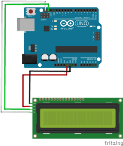
Setup In this part, we have to wire an LCM1602 IIC V1 to the Arduino. The LCM1602 has four pins: VCC, GND, SDA, and SCL. The wiring is straightforward: VCC goes to the Arduino’s 5V. The other three pins have the exact same names on the Arduino: GND goes to GND, SDA to SDA, and SCL to SCL. Have a look at the fritzing file for more details:
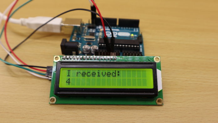
Arduino Source Code Next, we have to write some code for the Arduino Uno. Basically, the code just waits for bytes ready to be read by the serial port. If a byte was read, it is printed out to the LCM1602 IIC V1 module.
// (c) Michael Schoeffler 2017, http://www.mschoeffler.de #include #include // LiquidCrystal_I2C library LiquidCrystal_I2C lcd(0x27, 2, 1, 0, 4, 5, 6, 7, 3, POSITIVE); // 0x27 is the i2c address of the LCM1602 IIC v1 module (might differ) void setup() < lcd.begin(16, 2); // begins connection to the LCD module lcd.backlight(); // turns on the backlight lcd.clear(); Serial.begin(9600); while (!Serial) < ; // wait for serial port to connect. >lcd.setCursor(0, 0); // set cursor to first row lcd.print("Init done"); // print to lcd > void loop() < if (Serial.available() >0) < byte incomingByte = 0; incomingByte = Serial.read(); // read the incoming byte: if (incomingByte != -1) < // -1 means no data is available lcd.setCursor(0, 0); // set cursor to first row lcd.print("I received: "); // print out to LCD lcd.setCursor(0, 1); // set cursor to secon row lcd.print(incomingByte); // print out the retrieved value to the second row >> >
Java Source Code The Java application uses the jSerialComm library to send text to an Arduino Uno via a standard USB connection. I made use of Maven to set up the dependency between my Java project and the jSerialComm library. If you also use Maven for your project, then my POM file might be of use to you:
The actual Java source code is only a single class with a main method. A serial connection is established. Then, five digits (0-4) are written to the serial port. Finally, the serial connection is closed:
package de.mschoeffler.arduino.serialcomm.example01; import java.io.IOException; import com.fazecast.jSerialComm.SerialPort; /** * Simple application that is part of an tutorial. * The tutorial shows how to establish a serial connection between a Java and Arduino program. * @author Michael Schoeffler (www.mschoeffler.de) * */ public class Startup < public static void main(String[] args) throws IOException, InterruptedException < SerialPort sp = SerialPort.getCommPort("/dev/ttyACM1"); // device name TODO: must be changed sp.setComPortParameters(9600, 8, 1, 0); // default connection settings for Arduino sp.setComPortTimeouts(SerialPort.TIMEOUT_WRITE_BLOCKING, 0, 0); // block until bytes can be written if (sp.openPort()) < System.out.println("Port is open :)"); >else < System.out.println("Failed to open port :("); return; >for (Integer i = 0; i < 5; ++i) < sp.getOutputStream().write(i.byteValue()); sp.getOutputStream().flush(); System.out.println("Sent number: " + i); Thread.sleep(1000); >if (sp.closePort()) < System.out.println("Port is closed :)"); >else < System.out.println("Failed to close port :("); return; >> >
The main important method call is SerialPort.getCommPort(. ) . The method has only one argument which has to be the device name of your Arduino Uno. Therefore, it is very likely that you need to change this argument value. You can find out the device name of your Arduino Uno by having a look to the Arduino IDE. In Tools->Port you find all connected devices. In order to upload code to an Arduino, you have to select the correct device name of the corresponding Arduino. Luckily, the same device name is needed by the jSerialComm library. So simply copy the device name from your Arduino IDE to the Java source code.
Execution When you have uploaded the source code to the Arduino and started the java application, you should see that the digits 0-4 appear on the LCM1602 IIC V1 module. Sometimes, I have problems executing this code, if I use cheap Arduino clones. Luckily, it always executes perfectly on my original Arduino Uno from Italy 😉
Example 2
In the second part of this tutorial, the digits (coming from the Java application) are printed to the default serial connection of the Arduino. As a result, the received digits can be viewed from the Arduino IDE’s serial monitor (Tools -> Serial Monitor). Unfortunately, as a consequence, the standard USB connection cannot be used by the Java application since the serial monitor will already catch the serial port as soon as we open it. Therefore, we make use of a USB-to-TTL serial adapter.
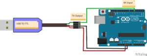
Setup Typically, a USB-to-TTL adapter has at least four pins: VCC, GND, RX (receive data), and TX (transmit data). As we will use this adapter only to send data from the Java application, we can ignore the RX pin. VCC must be connected to the Arduino’s 5V pin, GND must be connected to the Arduino’s GND pin, and TX must be connected to the Arduino digital pin #5 (also other digital pins can be used).
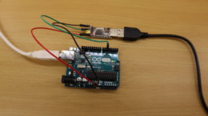
Here you see how my setup looks like (including the serial adapter):
Arduino Source Code: The Arduino program makes use of a so-called software serial. When a software serial object is initialized, it requires the pin numbers of the receive and transmit pin. As we do not plan to transmit text from the Arduino Uno, we can set the transmit pin to any number. Here, I simply set it to 6.
// (c) Michael Schoeffler 2017, http://www.mschoeffler.de #include SoftwareSerial sserial(5,6); // receive pin (used), transmit pin (unused) void setup() < Serial.begin(9600); // used for printing to serial monitor of the Arduino IDE sserial.begin(9600); // used to receive digits from the Java application while (!Serial) < ; // wait for serial port to connect. >> void loop() < if (sserial.available() >0) < byte incomingByte = 0; incomingByte = sserial.read(); if (incomingByte != -1) < Serial.print("I received: "); // print out to serial monitor Serial.println(incomingByte); // print out to serial monitor >> >
Java source code: The Java application is basically the same than the one used in part one of this tutorial. The only exception is the device name of the USB-to-TTL device. Conveniently, you can again make use of the Arduino IDE as it will show you the name of the serial adapter, too.
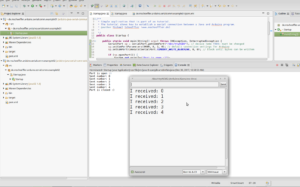
Execution: If everything was successfully executed, the serial monitor of the Arduino IDE should show five received digits.